home |  electronics |  toolbox |  science club |  tuxtalk |  photos |  e-cards |  online-shop

http://tuxgraphics.org/electronics


Content:
By Guido Socher


Pool timer

[Illustration]

Abstract:

We build a timer and a temperature sensor for a swimming pool and by combining the two into one unit we can simplify the installation of the temperature sensor.

This project is based on the 24h timer, a timer that repeats its program daily and can be programed very easily via a web-interface. It can be used from any smartphone or PC with a javascript capable web browser.

The pumps as used in swimming pools consume a lot of electricity. This is not because of the efficiency of the pump but because water is heavy and the pump requires the energy for the physical work to move the water mass around at high speed. It's a waste of energy to run the pump all day. To keep the water clean it is more than enough to run it for about 4-6 hours per day distributed over the day.

This web-based 24h timer is designed to control a swimming pool pump and measure air and water temperature. It plots the temperature history as as bar graphs. By combining the timer for the pump and the temperature sensors into one unit we have more flexibility in installing the temperature sensor. There is no need for a sensor in the pool water and the whole unit can be conveniently installed in a shed near the pump.

The base hardware is the tuxgraphics ethernet board. The software loaded into the board provides a web server with hardware control functions. You can operate this pool timer with a few mouse clicks for your PC or smartphone.


_________________ _________________ _________________


The two in one advantage

We could measure the water temperature by just running a cable with a temperature sensor to the pool and drop it in the water but that is not only a tripping hazard. It does not look good and causes the sensor to corrode over time.

By combining the pump control function and temperature measurement into one unit we know when water is flowing through the pipes to the pump and we can measure the temperature on the outside of the pipe coming from the pool's skimmer.

The water flows through the pipes at a fairly high speed and there is no time for it to cool even if the pipes are in ground. If we place the temperature sensor on the outside of the pipe and insulate that section very well then the temperature measurement done there provides exactly the same results as a temperature measurement in the pool would provide. We just have to wait about 5min after pump start to ensure that the temperature in the pipe is the same as the temperature at the sensor on the outside of the pipe. This is because the plastic pipes used for pools are not the best thermal conductors.

This way we can install the temperature sensor conveniently in the same place were all the other machinery for the pool is.  

What it looks like

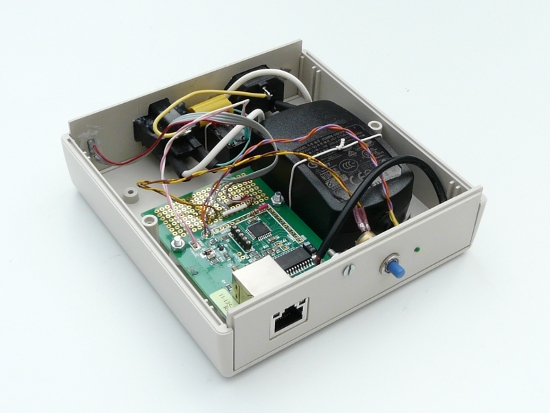
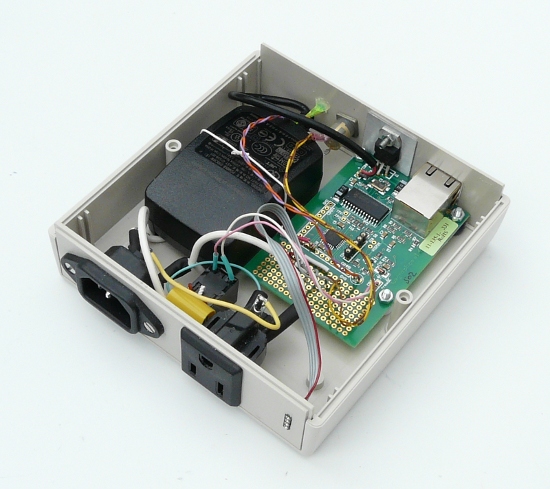
Here some pictures from the hardware. The tuxgraphics ethernet board is on the left. A 5V DC power supply is on the right, power connectors (in and out) are on the back with the relay in between. The push button on the front can be used to manually control the pump. This is in addition to the schedule that is programmed into the timer. The LED on the front is on when the output (pump) is on.

pool timer front view
pool timer hardware, front view.


pool timer back view
pool timer hardware, back view.

On the back you can see the connectors for power and a small connector for the temperature sensors. Everything that carries line power has been insulated with heat shrink tubing.

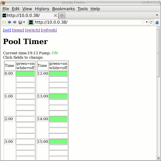
The next few screen shots provide an overview over the user interface.

pool timer, 24h timer user interface
24h timer user interface

You can program the schedule of this timer from any javascript capable web browser on a PC or smartphone. The timer can be programmed in 15min intervals. To activate or deactivate a given interval you just click on the field and it will toggle between green and white with green meaning "pump on". There is a password protection to prevent unauthorized changes.

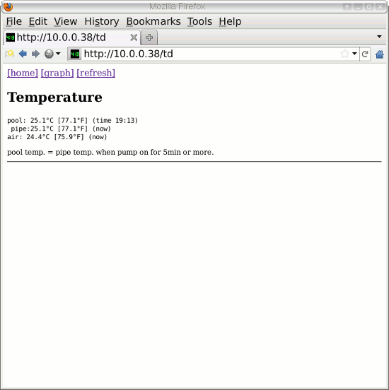
pool timer, air and water temperature

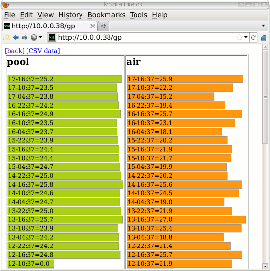
The temperature page shows readings for current outside air temperature and water temperature. The pool water temperature is measured at the outside of the pipe from the skimmer after the pump was running for at least 5min. If the pump is currently not running then the time behind the reading will indicate at what time the measurement was taken.

pool timer, temperature graphs for air and water

The system records historic data in graphical format and you can export it in column separated values format (CSV) to load it into a spread sheet. All the readings are initialized at power-on with zero and the first pool water reading is available after the pump was running for 5 minutes. You can configure the system for graphs in °C or °F.  

Installing the pool water sensor

We install the pool water sensor on the outside coming from the skimmer. I recommend to physically attach it on the side of the pipe. There might be an occasional air gap inside the pipe at the top and at the bottom you may have a bit of water on the outside of the pipe from humid air condensing at the pipe and then dripping down and running along the pipe. The below pictures show however the sensor at the top because it is easier to see that way.

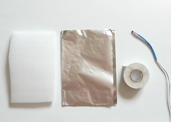
what you need: foam insulation pad, kitchen aluminum foil, tape and the sensor
What you need: foam insulation pad, kitchen aluminum foil, tape and the sensor


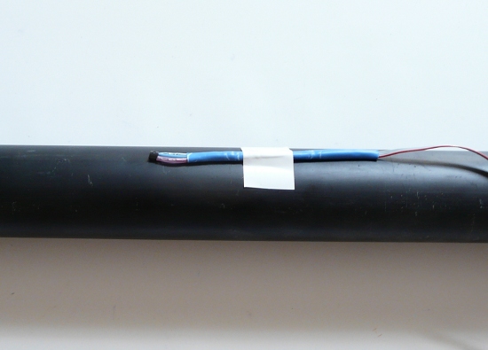
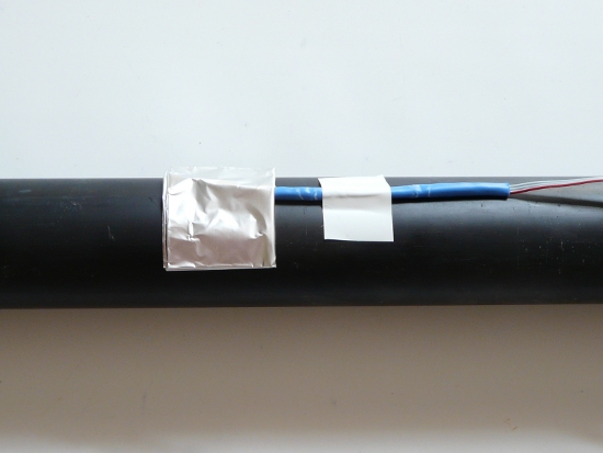
attach the sensor with a bit of tape to the outside of the pipe
Attach the sensor with a bit of tape to the outside of the pipe


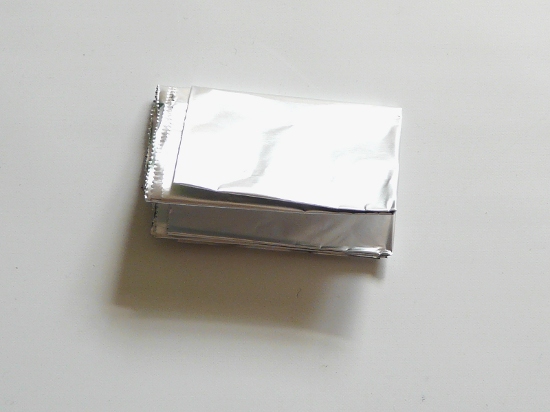
aluminum foil
Fold the aluminum foil several times. Aluminum foil is a good thermal conductor and it is flexible at the same time.


place the aluminum foil over the sensor
Place this thick pad of aluminum foil firmly over the sensor. You can wrap some tape around it to hold it in place.


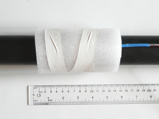
wrap insulation around and secure it tightly it with tape
Wrap insulation around the whole area and secure it tightly it with tape. You can get professional foam insulation, normally used for hot water pipes, at the hardware store.


Ethernet to the shed

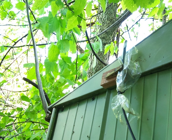
The pool equipment is usually installed inside a small shed in the garden. There is power but no network connection. I recommend to just use wifi and install the antenna on the outside of the shed. There may as well be enough signal strength inside the shed if the shed is made from wood or vinyl. The AVR WiFi article explains how to use wifi in combination with the tuxgraphics ethernet board.

wrap insulation around and secure it tightly it with tape
WiFi antenna on the outside of the garden shed for the pool-pump, filter system and the pool timer.


The relay to control the pump motor

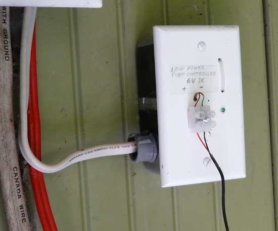
The pool pump motor is quite powerful and requires a good relay. To have such a fat relay and thick cables running next to sensitive electronics is not a good idea. I recommend to install a "fat relay" permanently in a box directly at the pump motor and attach an own fly-back diode and power supply (e.g a wall plug adapter from some old electronics or an old mobile phone charger) to that relay. The pool timer provides then power indirectly. It powers the power supply of the big pump relay. This prevents any interference and makes the pool timer a much lighter unit.


big relay at the pump
A big relay permanently installed by the pump. There is a 1N4001 fly-back diode soldered across the coil contacts of the relay. Polarity of the DC voltage powering the relay is therefore important. Both the relay and diode are inside the the grounded metal box. You might want to ask an electrician to do this installation for you.


The rating of the pump relay should correspond to the rating of the fuses for your pump. E.g: fuse rating 15A -> relay contact rating 15A or more, fuse rating 30A -> relay contact rating 30A or more (In Europe standard fuse ratings would normally be 10A and 16A respectively).

If you have a pump motor running on multiple phases (240V, 2 phases in the US/Canada or 400V, 3 phases in Europe) then just use one relay for each phase (=hot wire) and connect the coil contacts of all the relays in parallel such that you will still need only one DC voltage to control all the relays at the same time.  

The required ethernet hardware

This hardware is essentially a little web server with the possibility to control a relay for the pump and read temperature sensors. The software will run on any tuxgraphics ethernet board with an atmega328p or an atmega644/atmega644p.

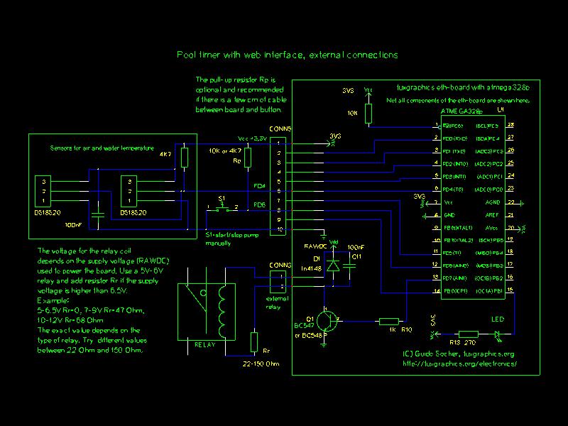
We use two DS18S20 which are already factory calibrated digital temperature sensors. They require a 4K7 pull-up resistor. I recommend to use a small 5-6V relay which can control loads of 5-10A. The tuxgraphics ethernet board has an open collector driver stage and a fly-back diode to control such a standard relay already on board. You can then permanently install a bigger relay suitable for the load of the pump motor directly at the pump. The relay directly at the pump is not shown here.

circuit diagram
circuit diagram: connections to the relay, LED (indicates state of the pump), 2xDS18s20 temperature sensors and a push button to manually control the pool pump.
Click on the image to view the diagram in pdf format
 

References/Download


© Guido Socher, tuxgraphics.org

2012-05-10, generated by tuxgrparser version 2.57